IN THIS ARTICLE
Creating and Simulating a PhysX Ragdoll
A ragdoll is a physical representation of a character in the animation system that you can use to simulate behavior, such as hit reactions and character death. The physical representation consists of a hierarchy of rigid bodies with simple shapes that are connected by joints. The animation system and the PhysX system work together to simulate the realistic behaviors. While the ragdoll setup occurs in the animation system, the PhysX system is responsible for how a character moves based on environmental interactions and external forces. For example, you can set up your ragdoll so that the character will rotate as it collapses when you apply force to the character’s outer shoulder area.
To use the PhysX Ragdoll , add it to an entity in O3DE Editor. You can then follow the procedures below to create and control the physical representation of the ragdoll.
Important:There is currently no automatic way to prevent the physics geometry PhysX Character Controller component from colliding with the PhysX Ragdoll component, which can lead to unexpected behavior for the ragdoll. Collisions can be avoided by using collision filtering or by disabling the physics on the PhysX Character Controller component when the ragdoll is activated.
This topic will teach you how to do the following:
Setting Up a Ragdoll
When you set up a ragdoll, you do the following:
In addition, your actor must have a motion extraction node that is a root node. Your ragdoll must have a root node that is a direct parent of the motion extraction node. For example, the Rin character uses root for its motion extraction node. For the ragdoll root node, the Rin character uses 'C_pelvis_JNT, which is a child node of root.
Step 1: Define Joints for the Ragdoll
Do the following to select the joints for your ragdoll.
To select joints for the ragdoll
In O3DE Editor, choose Tools, Animation Editor.
In the Animation Editor, on the right side of the menu bar, choose Physics from the drop-down list. This changes the layout.
Choose File, Open Actor and select your actor.
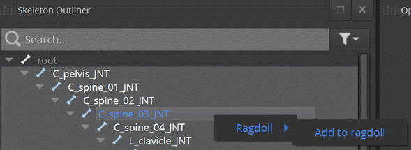
In the Skeleton Outliner, multi-select the joints that you want to include in your ragdoll.
Right-click one of the selected joints and then choose Ragdoll, Add to ragdoll.
Note:You can add joints to the ragdoll at any time.
- Click the filter icon next to the search text box, and select Ragdoll joints and colliders. This shows only the joints in the ragdoll and not the full animation skeleton.
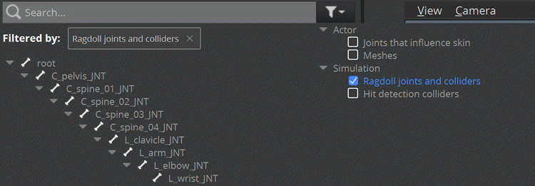
The Skeleton Outliner displays icons to indicate that:
- A joint is part of the ragdoll
- A joint holds ragdoll colliders
- A joint holds hit detection colliders
![]()
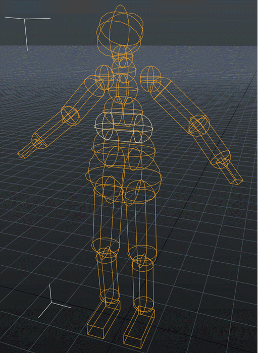
In the OpenGL Render window, use the render options to show or hide the ragdoll colliders (rendered in orange), ragdoll joint limits, and the hit detection colliders (rendered in blue).
Note:If your ragdoll colliders and hit detection colliders are the same size, you may need to hide the colliders that you are not working on.

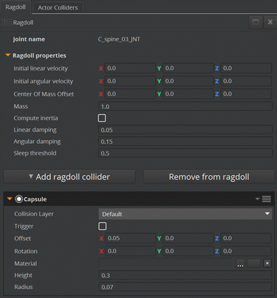
- On the Ragdoll tab, you can view and modify the ragdoll properties for the selected joint. For example, the rigid body mass, sleeping threshold, and colliders.
Step 2: Add Ragdoll Colliders
The ragdoll automatically suppresses collisions between joints that are adjacent in the skeleton. This means that adjacent colliders can overlap, but a pair of colliders that are not adjacent should not intersect. If the pair of colliders intersects, they’ll collide when the ragdoll is simulated.
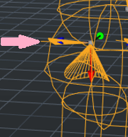
In the following example, the collider for the second spine joint (highlighted) can intersect with the first or third spine joint. The first and third spine joints, however, should not intersect.
To add a ragdoll collider
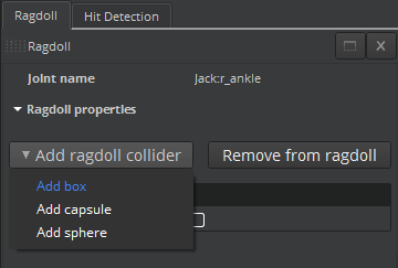
- In the Animation Editor, on the Ragdoll tab, click Add ragdoll collider and then choose Add box, Add capsule, or Add sphere.
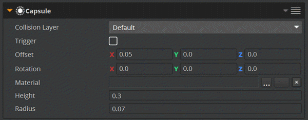
On the Ragdoll tab, do the following in the collider properties:
Set the Offset and Rotation to move the collider to the correct location. The Offset and Rotation are relative to the joint transform.
Adjust the collider dimensions (for example, set the Height and Radius for a Capsule) to resize the collider.
Choose File, Save Selected Actors. This saves the ragdoll data to the
.assetinfofile for the character. The Asset Processor then bakes the ragdoll data into the.actorfile.
Step 3: Create a Joint Limit
Joint limits are enabled for every joint in your ragdoll. This allows you to edit the joints and ensure they’re set up correctly.
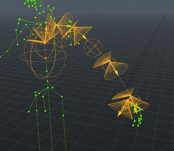
The following image shows joint limits that are set up correctly.
To create a joint limit
In the Animation Editor, in the OpenGL Render Window, adjust the child local rotation so that the red axis points along the bone.
Adjust the parent local rotation so that the red axis appears inside the swing cone.
Adjust the twist limit value so that the line appears inside the wedge.
Adding Your Ragdoll to an Animation Graph
When you create an animation graph to control the ragdoll simulation of your character, you do the following:
- Prepare the actor asset.
- Adjust the animation graph to enable the ragdoll.
- Preview
The animation graph controls the ragdoll simulation of your character. When your character transitions into a blend tree that has a ragdoll node, the ragdoll automatically activates and simulates in game mode in O3DE Editor. When your character transitions out of that state, the ragdoll deactivates. The ragdoll node outputs a bind pose in the Animation Editor.
To create an animation graph to transition from running state to ragdoll state
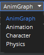
- In the Animation Editor, on the right side of the menu bar, choose AnimGraph from the drop-down list. This changes the layout.
In the Anim Graph pane, click the + icon to create a new animation graph.
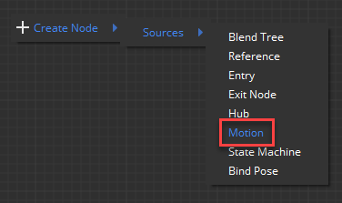
Right-click the grid and then choose Create Node, Sources, Motion. Alternatively, in the Anim Graph Palette, on the Sources tab, drag Motion into the animation graph.
Select the Motion node in the animation graph.
In the Attributes pane, do the following:
For Name, enter a name for your motion. For example, Run.
Click Select motions. In the Motion Selection window, select a motion and then click OK.
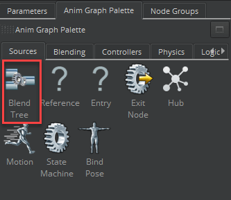
Right-click the grid and then choose Create Node, Sources, Blend Tree. Alternatively, in the Anim Graph Palette, on the Sources tab, drag Blend Tree into the animation graph.
Select the Blend Tree node in the animation graph.
In the Attributes pane, enter a name for your blend tree. For example, Ragdoll.
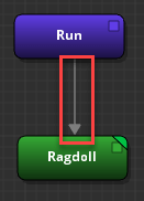
In the animation graph, connect the Motion node to the Blend Tree node. For example, connect the Run node to the Ragdoll node.
Double-click the Blend Tree node.
Right-click the grid and then choose Create Node, Sources, Ragdoll. Alternatively, in the Anim Graph Palette, on the Sources tab, drag Ragdoll into the animation graph.
Connect the Output Pose for the Ragdoll node to the Input Pose for the Final Node node.
At the root of the animation graph, select the transition line that starts from the Motion node and connects to the Blend Tree node. For example, select the transition line that connects the Run node to the Ragdoll node.
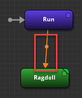
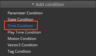
In the Attributes pane, click Add condition and then choose Time Condition.
Under Time Condition, set the Countdown Time.
- In the animation graph, click the Motion node for a preview.
Simulating Your Ragdoll
Once you’ve created your ragdoll and animation graph, you can simulate the ragdoll in game mode in O3DE Editor.
To simulate your ragdoll
In O3DE Editor, right-click the viewport and choose Create entity.
In the Entity Inspector, for Name, enter Ragdoll.
Add an Actor component:
Click Add Component, Actor.
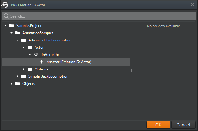
In the Actor component, for Actor asset, click the browse (…) button.
In the Pick EMotion FX Actor window, select the actor for which you set up the ragdoll and then click OK.
Add an Anim Graph component:
Click Add Component, Anim Graph.
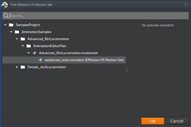
In the Anim Graph component, for Motion set asset, click the browse (…) button.
In the Pick EMotion FX Motion Set window, select your motion set and then click OK.
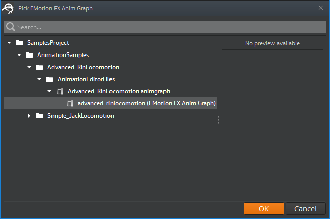
In the Anim Graph component, for Anim graph, click the browse (…) button.
In the Pick EMotion FX Anim Graph window, select your animation graph and then click OK.
Click Add Component, PhysX Ragdoll.
To start the level and simulate your ragdoll, press Ctrl+G.